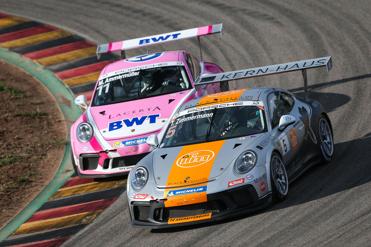
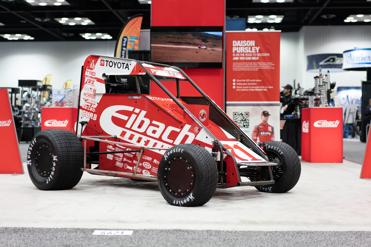
ERS System Race Spring System
Endless Combinations
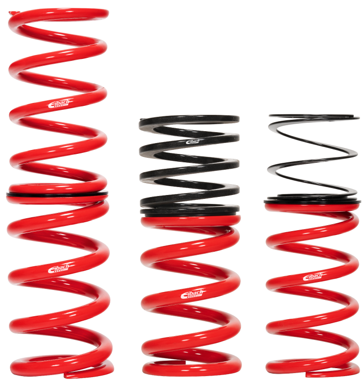
By combining Eibach Main, Tender and/or Helper springs, the suspension engineer or weekend racer can create the perfect combination of spring rates for the ultimate suspension set-up. With our extensive range of motorsport spring sizes and rates - over 1,400 different options - our ERS system is unsurpassed in performance and flexibility.
Dual Spring System
Suspension tuning is a precise balance. On one hand, the spring system should be soft enough to absorb track irregularities assuring maximum adhesion, while on the other hand the spring system must be firm enough to reduce the body roll, squat, and dive of the vehicle during cornering, acceleration and braking. For optimum balance, a dual-spring system can be used.


Main & Tender System
The Eibach Main and Tender Spring concept provides a softer initial rate when both springs are compressed together, then delivers the desired firmer final rate once the tender spring closes completely. The Main Spring has a linear-rate characteristic and determines the final rate of the system. The Tender Springs are available in linear or progressive-rate and determine the initial rate of the spring system.
Main & Helper System
A Helper Spring is used to prevent the Main Spring from becoming loose in the spring seat when the suspension is unloaded or at full droop. The Helper Spring, unlike the Tender Spring, has very little spring rate, and therefore has no effect on the suspension characteristics of the vehicle. Up to 6” (150mm) of spring-to-perch gap can be covered with the use of a Helper Spring.


Bump & Spring Rubber System
Through on-track development, Eibach has engineered a spring and cap system light weight and compact enough to fit Pavement Series setups, with maximum amounts of linear travel needed for Dirt Series Racers. The Consistent performance of the Eibach Bump Spring system translates to increased aero efficiency, maximum grip and superior control at the limit.
The Eibach Main and Spring Rubber system allows you to add progressive rate to your linear Main spring allowing you to precisely tune your spring characteristics on the track without having to disassemble any suspension components saving you important setup time.

Multi-Spring Systems
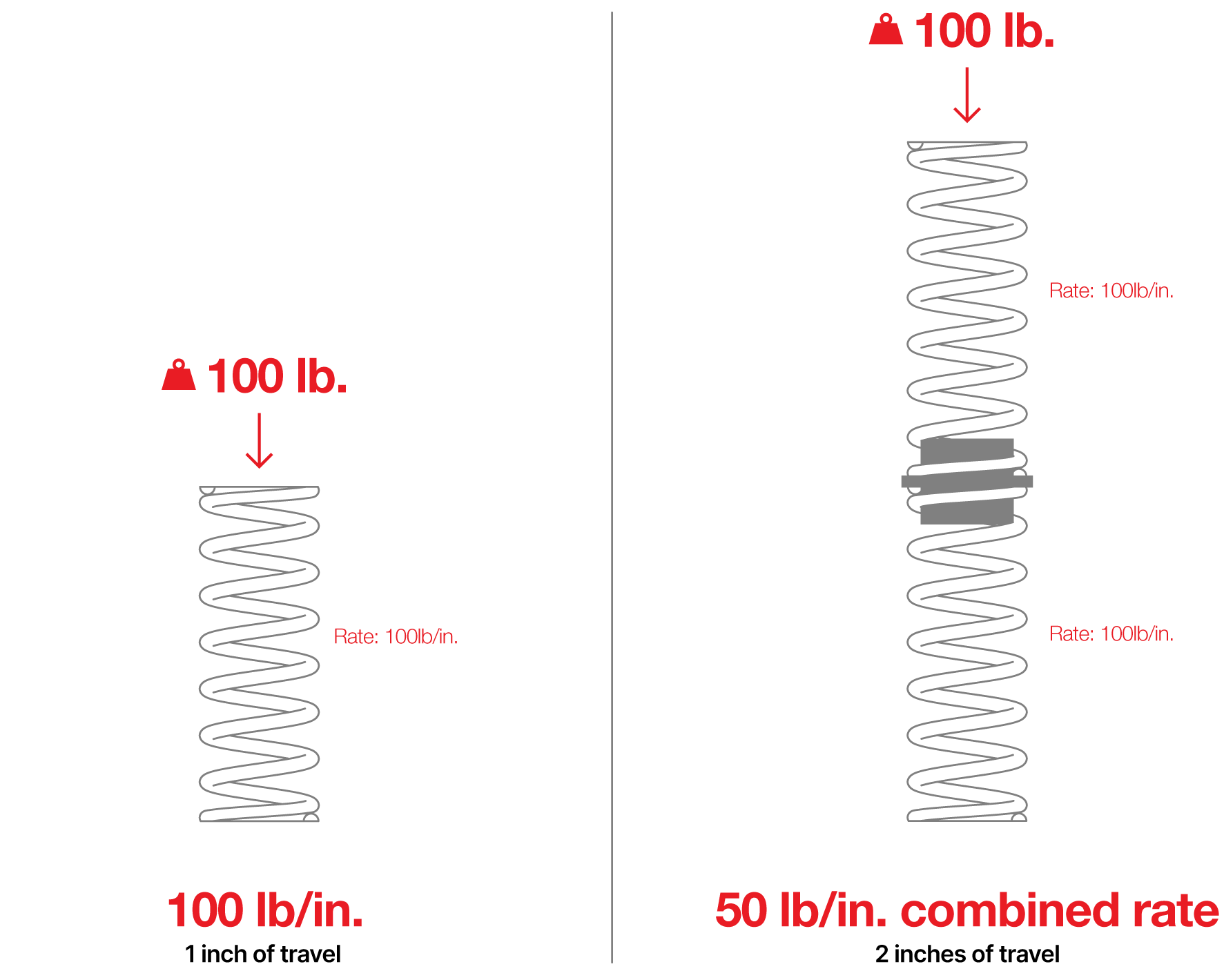
Spring Rate is defined as the amount of force required to move the spring a given distance, which means a 100lb/in spring will travel 1 inch for every 100lb of force exerted on the spring.
In a multi-spring system, the misconception is that the first spring will carry the entire load before the second spring begins to compress. This is untrue. In the example below, two 100lb/in springs are stacked. Each spring will still move one inch for every 100lb of force. With these factors, the combined rate of a multi-spring system can be determined.
(K1 + K2)
Block Transition System
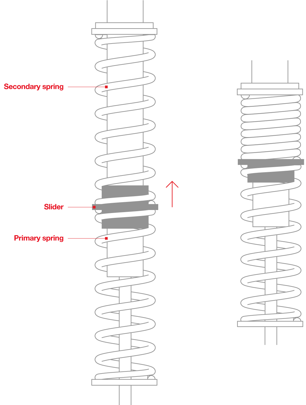
In a multi-rate system, the rate transition must be taken into consideration. There are two ways to achieve this transition. In the first method, the softer upper (Secondary) spring is allowed to coil bind or “block”. This is the moment of transition to the Primary spring's characteristics alone.
Forced Transition System
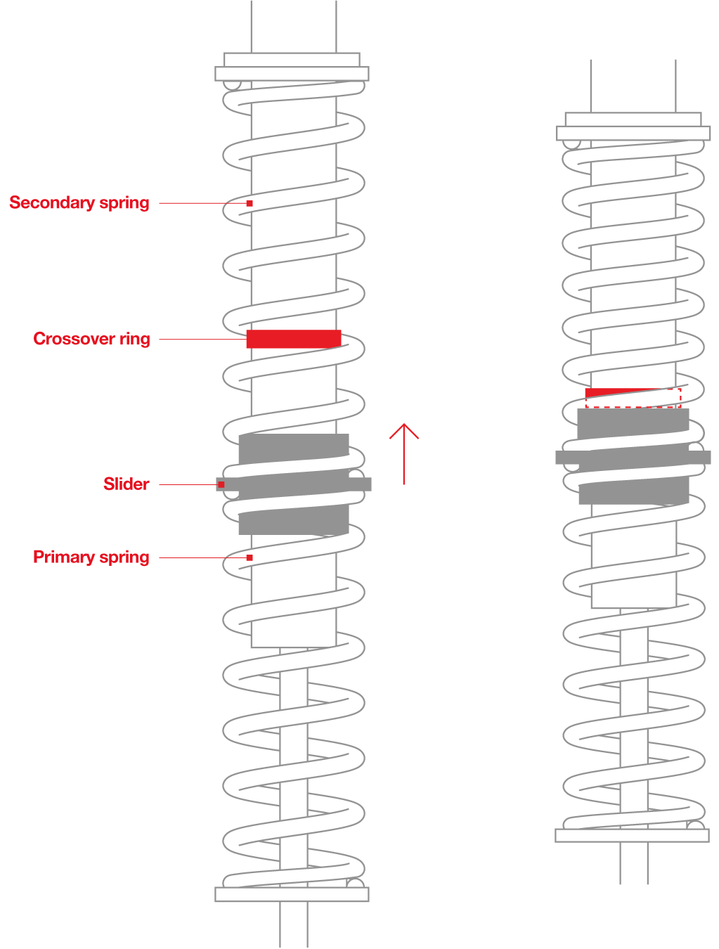
The second method is to utilize a forced transition. This is most commonly achieved with a crossover ring. The crossover ring threads on the shock body allowing the tuner to adjust the point at which the slider (spring coupler) makes contact and stops the compression of the Secondary spring.
This is superior as it allows for the tuner to select from a vast range of transition points, thus creating the most efficient use of the travel.
Single Linear Spring
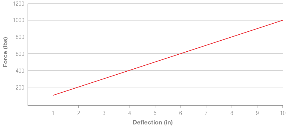
This graph demonstrates a single 10” 100lb/in spring through it’s travel range.
Block Transition System
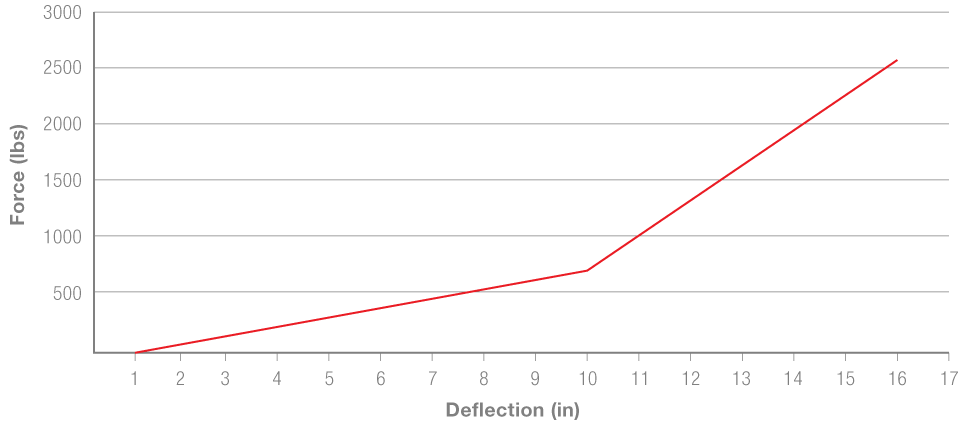
This graph shows a dual-rate system using a 10" 100lb/in spring stacked on a 16" 300lb/in spring. This demonstrates the transition that occurs when the 10" 100lb/in spring reaches its block height. This allows for a softer initial rate for smoothness on smaller bumps with a stronger final rate for big jumps or full compression scenarios.
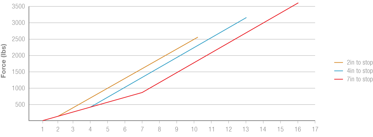
Forced Transition (at Different Positions)
This last graph demonstrates a 10" 300lb/in stacked on a 16" 300lb/in spring. The three different rate curves show the effect that the position of the stop ring has on the transition of the rate. Notice that as you decrease the travel of the secondary spring (block the initial rate out sooner), the travel of the overall stacked system decreases. Comparing the curves side by side demonstrates the control that a proper dual-rate combination provides over travel and rate transition.
